
Polo Mk5
 Note
Note
|

| Special tools and workshop equipment required |
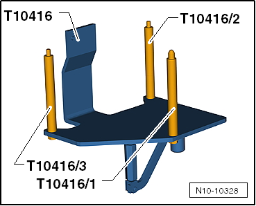
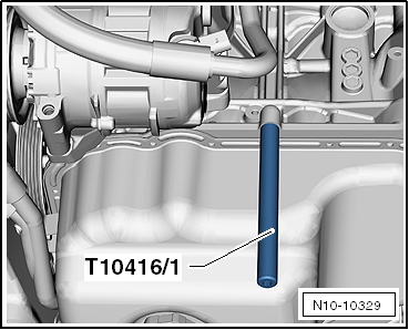
| t | Engine support -T10416- with adapters /1, /2, /3 |
| t | Torque wrench -V.A.G 1331- |
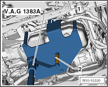
| t | Engine and gearbox jack -V.A.G 1383 A- |
| t | Engine and gearbox support -VAS 6095- |
| t | Drip tray for workshop hoist -VAS 6208- |
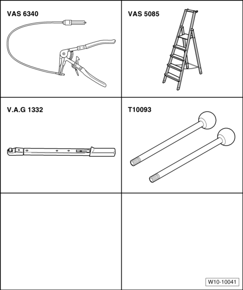
| t | Hose clip pliers -VAS 6340- |
| t | Stepladder -VAS 5085- |
| t | Torque wrench (40 … 200 Nm) -V.A.G. 1332- |
| t | Guide rods -T10093- |
Note
|
|
|
|
|
|
|
 WARNING
|
|
|
|
|
|
|
|
|
|
|
|
|
|
|
|
|
|
|
|
|
|
 Caution
Note
Note
|
|
|
|
|
|
Note
Note
|
|
|
|
Note
|
|