
Polo Mk4
|
 WARNING
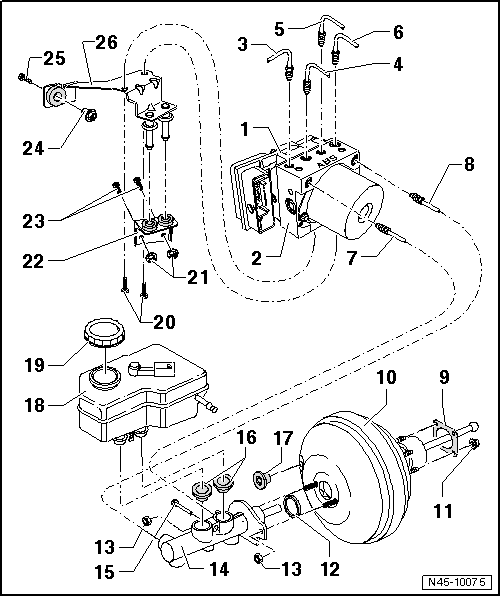
| 1 - | ABS control unit -J104- |
| q | remove and install the ABS hydraulic unit -N55- with theABS control unit -J104 - → Chapter. |
| 2 - | Hydraulic ABS unit -N55- |
| q | TheABS reflux pump -V39- and the coupled valves must not be separated. |
| q | When replacing the hydraulic unit, seal the old part with the plugs from the repair set number ET 1H0 698 311 A |
| q | remove and install the ABS hydraulic unit -N55- with theABS control unit -J104 - → Chapter. |
| 3 - | Brake pipe connection |
| q | Hydraulic unit for right front brake caliper |
| q | Identification in the hydraulic unit -VR- |
| 4 - | Brake pipe connection |
| q | for the left rear brake caliper |
| q | Identification in the hydraulic unit -HL- |
| 5 - | Brake pipe connection |
| q | for the right rear brake caliper |
| q | Identification in the hydraulic unit -HR- |
| 6 - | Brake pipe connection |
| q | Hydraulic unit for left front brake caliper |
| q | Identification in the hydraulic unit -VL- |
| 7 - | Brake cylinder connection |
| q | Brake cylinder/floating plunger loop for the hydraulic unit |
| q | Identification in the hydraulic unit -HZ1- |
| 8 - | Brake cylinder connection |
| q | Brake cylinder/floating plunger loop for the hydraulic unit |
| q | Identification in the hydraulic unit -HZ2-- |
| 9 - | Sealing |
| q | to servo brake |
| 10 - | Servo brake |
| q | On gasoline engines, the vacuum required is removed from the intake manifold. |
| q | On diesel engines, a vacuum pump is installed to create vacuum |
| q | Operation checking: |
| – | Press the brake pedal several times until the end with the engine stopped (This eliminates any remaining vacuum inside the device). |
| – | Now, keep the brake pedal pressed in the braking position with medium force and start the engine. When the servo brake is working correctly, it can be felt with a foot on the brake pedal (the amplification is active). |
| q | In case of faults, replace completely |
| q | Check valve (in the flexible vacuum tube) → Chapter |
| q | separate from the brake pedal → Chapter. |
| q | disassemble and assemble → Chapter |
| 11 - | Self-locking hex head nut |
| q | replace |
| q | 28 Nm |
| 12 - | Sealing ring |
| q | replace |
| 13 - | Self-locking hex head nut |
| q | replace |
| q | 20 Nm |
| 14 - | Brake cylinder |
| q | cannot be repaired. Where faults occur, replace completely. |
| q | remove and install → Chapter |
| 15 - | Retaining pin for the brake fluid reservoir |
| q | insert through the brake cylinder |
| 16 - | Sealing plug |
| q | moisten with brake fluid and press in the brake cylinder |
| 17 - | Sealing plug |
| q | connection to flexible vacuum tube |
| 18 - | Brake fluid reservoir |
| 19 - | Plug |
| 20 - | Screws |
| q | 8 Nm |
| 21 - | Self-locking hex head nut |
| q | replace |
| q | 20 Nm |
| 22 - | Support |
| 23 - | Stud |
| q | Stud welded to the body |
| 24 - | Self-locking hex head nut |
| q | replace |
| q | 20 Nm |
| 25 - | Stud |
| q | Stud welded to the body |
| 26 - | Support |