volkswagen Workshop Repair Guides

Volkswagen Workshop Service and Repair Manuals

Servicing clutch housing > < Dismantling and assembling gearbox
5-speed manual gearbox 085
Dismantling and assembling gearbox
Dismantling and assembling sequence
 
V34-2039

Dismantling and assembling gearbox housing cover, gearbox housing, selector mechanism, input shaft, output shaft (pinion shaft), differential and selector forks

Dismantling

  • ‒ → Mount gearbox on repair stand.
  • ‒ Drain gearbox oil.
 
N30-0097
  • ‒ → Remove clutch release lever -A- with release bearing -B-.
  • ‒ Remove guide sleeve -C-.
 
V34-2737
  • ‒ → Remove both flanged shafts.
  • ‒ Take out flanged shafts along with springs, thrust washers and tapered rings.
  • ‒ Unbolt gearbox housing cover and take off along with seal.
 
N34-0155
  • ‒ Screw selector finger onto selector shaft.
  • ‒ → Select 5th gear (arrows 1 and 2).
 
V34-2738
  • ‒ → Loosen lock nut (arrow A) below 5th gear fork.
  • ‒ Unbolt ball head bolt (arrow B) and remove selector fork together with 5th gear locking collar.
 
N34-0156
  • ‒ Slide locking collar again over synchro-hub.
  • ‒ → Remove bolt -A- for 5th gear by selecting 5th (arrow 1) and 2nd gear (arrows 2 and 3).
  • ‒ After engaging both gears the input shaft and output shaft are locked, synchro-hub and gear cannot turn. The bolt can now be loosened.
  • ‒ Take off 5th gear synchro-hub and take out 2nd gear.
 
V34-2739
  • ‒ → Take off securing ring (arrow) for synchro-hub
 
V34-2740
  • ‒ → Pull off synchro-hub with 5th selector gear.
  • A - Two arm puller e.g. Kukko 20/10 with Matra V/170 hooks.
 
V34-2741
  • ‒ → Remove needle roller bearing (arrow).
 
V34-2744
  • ‒ → Pull off 5th gear
  • A - Two arm puller e.g. Kukko 20/10 with Matra V/170 hooks.
  • B - Hexagon bolt M8 x 15 (13 mm AF).
  • Sequence for removing:
    Fit two arm puller and centralize by turning screw (arrow). Heat gear wheel with hot air blower V.A.G 1416 and pull off.

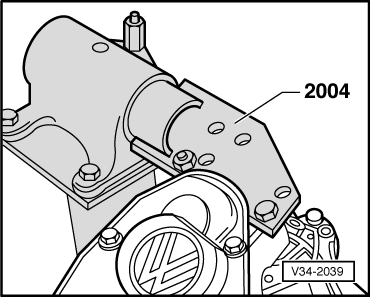
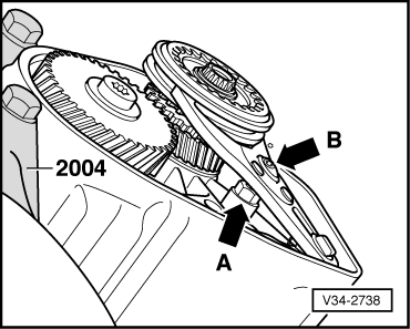
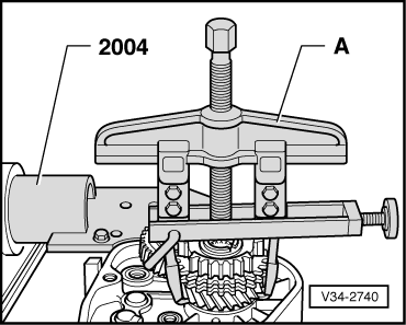
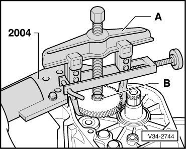
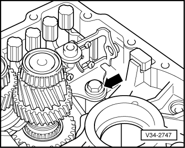
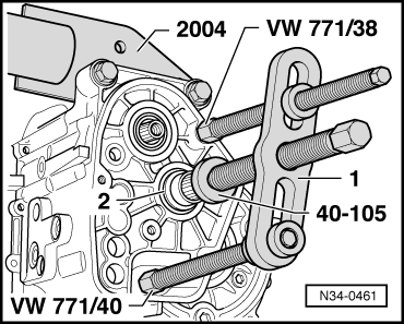
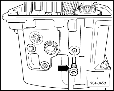
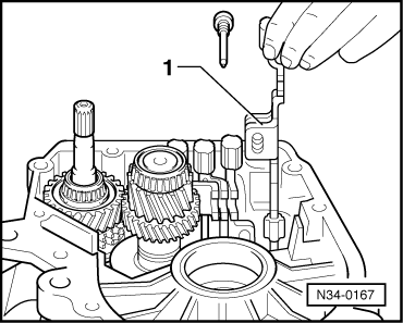
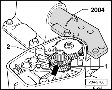
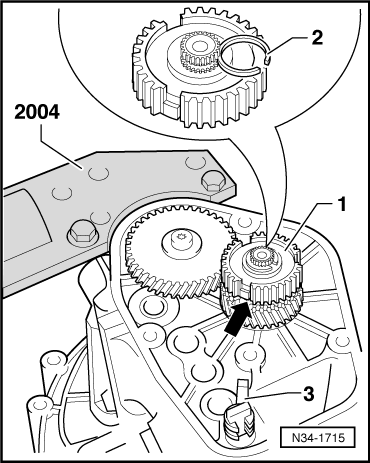
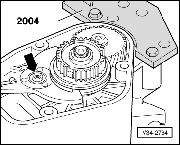
Note:

When pulling off the gear wheel ensure that the hooks do not bend outwards, if necessary tighten screw (arrow). After 5th gear wheel has been removed check for damage.

 
V34-2745
  • ‒ → Squeeze clip together (arrow) and take off.
  • ‒ Remove clutch housing securing bolts.
  • ‒ Take off clutch housing.
  • ‒ Take differential off gearbox housing.
 
N34-0454
  • ‒ → Pull sealing plugs out.
 
V34-1708
  • ‒ → Pull out selector shaft, drive out with a drift if necessary.
 
N34-0159
  • ‒ → Remove spring (arrow) between selector finger -A- and selector console -B-.
  • ‒ Remove selector finger -A-.
 
V34-2747
  • ‒ → Remove bolt (arrow) and take out selector console with bush.
 
N34-0452
  • ‒ → Remove reversing light switch -1- and reverse gear securing bolts -2-, -3- and -4-.
 
V34-2749
  • ‒ → Remove 5th gear selector rod -1- and reverse gear selector rod -2- with reverse lever -3-.
 
N34-0461
  • ‒ Turn gearbox in installation position
  • ‒ → Press out output shaft with puller -1- e.g. Kukko 18/1. The taper roller bearing outer race -2- is pressed out of the housing when doing this.
 
V34-2750
  • ‒ → Drive out reverse gear shaft -1-.
  • ‒ Take out input shaft -5 -, output shaft -4-, 1st and 2nd gear selector rod -3-, 3rd and 4th gear selector rod -6- as well as reverse gear -2- and shaft -1- from gearbox housing.

Assembling

 
V34-2751
  • ‒ Press output shaft taper roller bearing outer race into gearbox housing .
  • ‒ → Insert output shaft -3- with 1st and 2nd gear selector rod -4-.
  • ‒ Slide reverse gear -1- over shaft -2- and insert shaft.
 
V34-2752
  • ‒ → Lift up reverse gear so that the reverse gear lever can be inserted later.
 
V34-2753
  • ‒ → Lift up output shaft -1- with 1st and 2nd gear selector rod slightly and insert again together with input shaft -3- as well as 3rd and 4th gear selector rod -4-.

Notes:

  • ◆ Reverse gear wheel remains lifted with VW 681.
  • ◆ Guide input shaft with 3rd and 4th gear past output shaft 4th gear during insertion.
 
N34-0453
  • ‒ → Secure shaft for reverse gear.
 
N34-0165
  • ‒ → Insert reverse gear lever -1- into reverse gear selector rod -2-.
  • ‒ Install components, but first insert reverse gear lever into reverse gear.
 
N34-0465
  • ‒ → Secure reverse gear lever (arrow).
  • ‒ Remove special tool VW 681 from gearbox housing.
 
N34-0167
  • ‒ → Install 5th gear selector fork -1- and secure.
 
V34-2756
  • ‒ → Bring selector rods -A- into neutral.
  • ‒ Install selector console -B- with bush and bolt.
  • ‒ Align selector console -B-, to do this insert selector shaft -C- and tighten bolt -arrow-.
  • ‒ Remove selector shaft -C- again.
 
N34-0168
  • ‒ → Insert selector finger -1- in selector console -2-.
 
V34-2757
  • ‒ → Insert spring (arrow) between selector finger -1- and selector console -2-.
  • ‒ Push selector shaft -3- into selector finger and selector console.

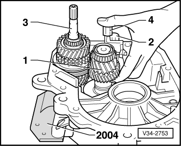
Installation position:

The step points towards input and output shafts.

  • ‒ Drive sealing plug -4- in flush.
  • ‒ If necessary adjust selector finger and selector sleeve =>
    Page 34-114 .
  • ‒ Install differential.
  • ‒ Fit gearbox housing.
 
V34-2043
  • ‒ Fit reversing light switch.
  • ‒ Install springs, thrust washers, tapered rings and flange shafts. Observe differences between flange shafts.

→ Differences

Item

Flanged shaft

Dimension "a"

1

Left, gearbox housing side

57 mm

2

Right, clutch housing side

48 mm

 
V34-2758

Installation position of 5th gear

The recess on internal diameter faces gearbox housing.

  • ‒ → Knock-on 5th gear.
 
N34-0169
  • ‒ → Screw-in new 5th gear securing bolt -1- with dished spring -2-.

Installation position of dished spring for 5th gear securing bolt:

The outer diameter (concave side) faces 5th gear.

  • ‒ Install thrust washer -3- for 5th gear sliding wheel.

Installation position:

Recess on thrust washer internal diameter faces towards needle roller bearing.

  • ‒ Heat sleeve -4- for 5th gear needle roller bearing to approx. 100°C on a hot plate then drive on.
 
V34-2760
  • ‒ → Install 5th selector gear -1- with needle roller bearing
  • ‒ Install spring (arrow) on 5th gear synchro-ring.
  • ‒ Place 5th gear synchro-ring on gear wheel
 
V34-2761

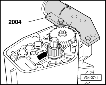
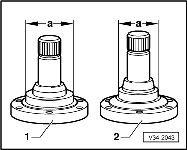
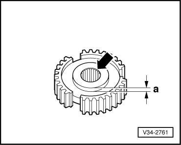
→ Installation position of 5th gear synchro-hub

The high shoulder of the synchro-hub (dimension -a-) faces towards gearbox housing.

 
N34-1715
  • ‒ → Drive on 5th gear synchro-hub -1- with tool 30-23.

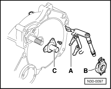
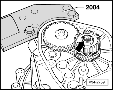
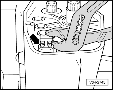
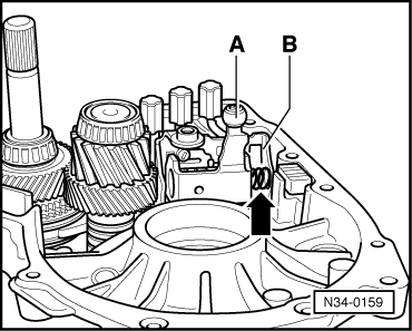
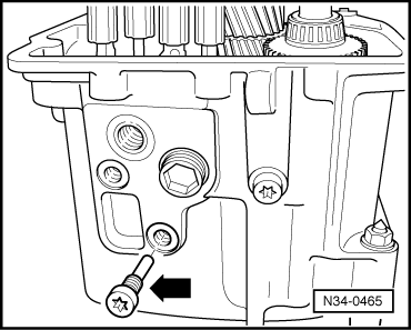
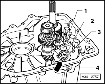
Note:

When driving synchro-hub on ensure synchro-ring is free to move.

The locking piece (arrow) must sit in the synchro-ring recess.

  • ‒ Determine new circlip -2-.
  • ‒ Determine and insert circlip -the thickest one that just fits in-.

Available circlips

Thickness (mm)

Part No.

2.00

085 311 187

2.10

085 311 187 A

2.20

085 311 187 B

2.30

085 311 187 C

2.40

085 311 187 D

2.50

085 311 187 E

2.60

085 311 187 F

  • ‒ Squeeze clip -3- together and insert on 5th gear selector rod.
 
V34-2763

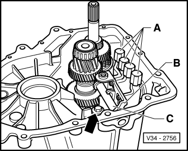
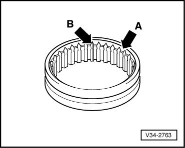
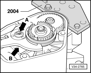
→ Installation position of 5th gear locking collar

Install teeth points (arrow A) towards 5th selector gear.

  • ‒ The marked splines (arrow B) are to be inserted into the recesses on the synchro-hub.
 
N34-0156
  • ‒ → Tighten 5th gear bolt -A-, to do this select 5th (arrow 1) and 2nd gear (arrows 2 and 3).
  • ‒ Remove locking collar again.
 
V34-2738
  • ‒ Clean ball stud threads in housing, use an M8x1 thread tap if necessary.
  • ‒ Insert locking collar together with 5th gear selector rod.
  • ‒ → Turn back lock nut (arrow A) below 5th gear selector rod.
  • ‒ Screw in ball headed bolt (arrow B).

Adjusting 5th gear:

Basic setting

  • ‒ Coat threads on ball head bolt with locking fluid D 000 600.
 
V34-2764
  • ‒ Turn gearbox to installation position.
  • ‒ All selector rods in neutral.
  • ‒ Loosen ball head bolt lock nut.
  • ‒ → Adjust ball head bolt (arrow) so that the locking collar is flush with the synchro-hub.

Fine adjustment

  • ‒ Select 5th gear.
 
V34-2765
  • ‒ → Turn ball head bolt (arrow A) in so far so that there is no axial play in the locking collar groove for 5th gear selector fork.
  • ‒ Then turn ball head bolt (arrow A) back so that play can just be felt between locking collar and selector fork (approx.1/8 turn).
  • ‒ Lock ball head bolt (arrow A) with lock nut (arrow B) below 5th gear fork to gearbox housing, ensuring that the ball head bolt has not turned.
  • ‒ Disengage 5th gear. Locking collar must now be in the neutral position. Synchro-ring must move freely.
  • ‒ Fit seal.
  • ‒ Fit gearbox housing cover

Servicing clutch housing > < Dismantling and assembling gearbox