Volkswagen Workshop Service and Repair Manuals
HOME
FEATURES
MENU
INDEX
ABOUT US
Removing and installing exhaust gas temperature sender 3G495 >
< Removing and installing exhaust gas temperature sender
Golf Mk6
Power unit
4-cylinder diesel engine (2.0 l engine, common rail, generation II)
Exhaust system
Exhaust gas temperature regulation / moving_and_installing_exhaust_gas_temperature_sender/">Removing and installing exhaust gas temperature sender
Removing and installing exhaust gas temperature sender 1G235
Removing and installing exhaust gas temperature sender 1G235
Removing and installing exhaust gas temperature sender 1 -G235-
Special tools and workshop equipment required
t
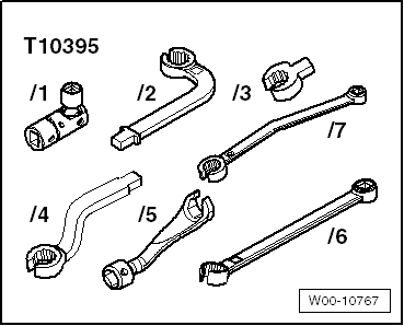
Tool set, 17 mm -T10395-
Removing
–
Disconnect electrical connector
-3-
for exhaust temperature sender 1 -G235- and free electrical line.
Note
The threaded connection is accessible from below.
–
Unscrew exhaust temperature sender 1 -G235-
-item 1-
from exhaust manifold.
Installing
l
Specified torque
→ Chapter „Assembly overview - exhaust gas temperature regulation“
.
Installation is carried out in the reverse order; note the following:
Note
t
Coat thread of exhaust gas temperature sender with high-temperature paste; high-temperature paste
→ Electronic parts catalogue
.
t
Fit cable tie in same place when installing.
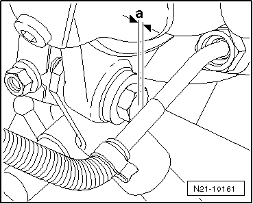
Installation position of exhaust gas temperature sender -G235-.
l
Angled shaft must have a distance
-a-
= 3 … 5 mm to bolting of turbocharger support.
–
Electrical connections and routing
→ Current flow diagrams, Electrical fault finding and Fitting locations
.
Power unit
4-cylinder diesel engine (2.0 l engine, common rail, generation II)
Exhaust system
Exhaust gas temperature regulation / moving_and_installing_exhaust_gas_temperature_sender/">Removing and installing exhaust gas temperature sender
Removing and installing exhaust gas temperature sender 1G235
Removing and installing exhaust gas temperature sender 3G495 >
< Removing and installing exhaust gas temperature sender
 Note
Note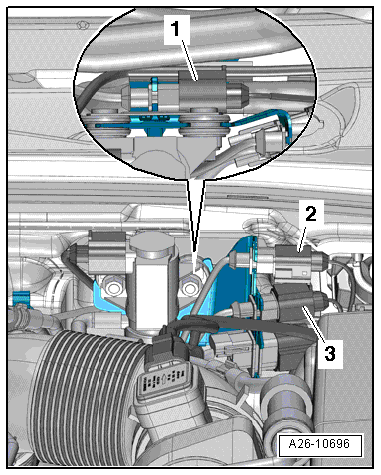 Note
Note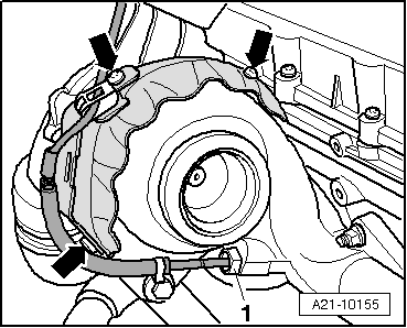
 Note
Note
Note
Note