volkswagen Workshop Repair Guides

Volkswagen Workshop Service and Repair Manuals

Checking additional signals > < Checking function
Checking intake manifold flap motorV157
Checking intake manifold flap motor -V157-
Engine codes AGP, AQM
Special tools and workshop equipment required
t  Fault reader -V.A.G 1551- or vehicle system tester -V.A.G 1552- with diagnosis cable -V.A.G 1551/3-
t  Adapter cable, 121-pin -V.A.G 1598/31-
t  Hand multimeter -V.A.G 1526C- or multimeter -V.A.G 1715-
t  Auxiliary measuring set -V.A.G 1594C-
t  Current flow diagram
Test procedure
–  Connect fault reader -V.A.G 1551- or vehicle system tester -V.A.G 1552- and select engine electronics control unit with “address word” 01. Engine must be idling. (Connecting fault reader and selecting engine electronics control unit → Chapter.)
   
Indicated on display:
–  Press buttons 0 and 3 for function “Final control diagnosis”.
 
Rapid data transfer                 HELP
Select function XX                    
Indicated on display:
–  Confirm entry with Q button.
 
Rapid data transfer                    Q
03-Final control diagnosis                   
Indicated on display:
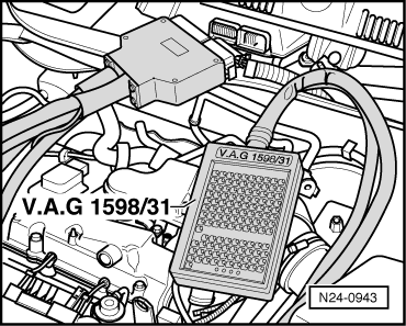
Activating the intake manifold flap motor -V157- alternatingly changes the combustion noise (the positioning motor opens and closes the intake manifold flap).
If no changes to combustion noises can be heard:
–  Press the C button.
–  Press buttons 0 and 6 for function “End data transfer” and confirm entry with Q button.
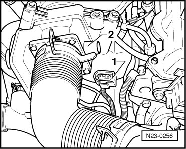
–  Switch off ignition.
 
Final control diagnosis               ->
Intake manifold flap motor V157        
–  Pull connector -1- off intake manifold flap motor -V157--2-.
–  Switch on ignition.
  N23-0256
–  Measure supply voltage at intake manifold flap motor -V157- connector contact 4 and at motor earth, then at contacts 4 and 1 of connector.
Specification: approx. battery voltage
If the specification is not achieved:
–  Switch off ignition.
  A24-0094
–  Connect adapter cable, 121-pin -V.A.G 1598/31- to control unit wiring harness.
–  Check wiring between 121-pin adapter cable -V.A.G 1598/31- and connector for open circuit referring to current flow diagram.
Contact 2+ socket 81 Contact 3+ socket 75 Line resistance: max. 1.5 Ω
–  Also check wiring for short to one another, short to vehicle earth and short to battery positive.
Specification: ∞ Ω.
If no fault in lines is detected:
–  Renew diesel direct injection system control unit -J248- → Chapter.
  N24-0943

Checking additional signals > < Checking function