Golf Mk3
|
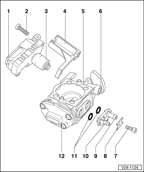
Mono-Motronic injection and ignition system
Servicing injection unit
|
 |
|
|
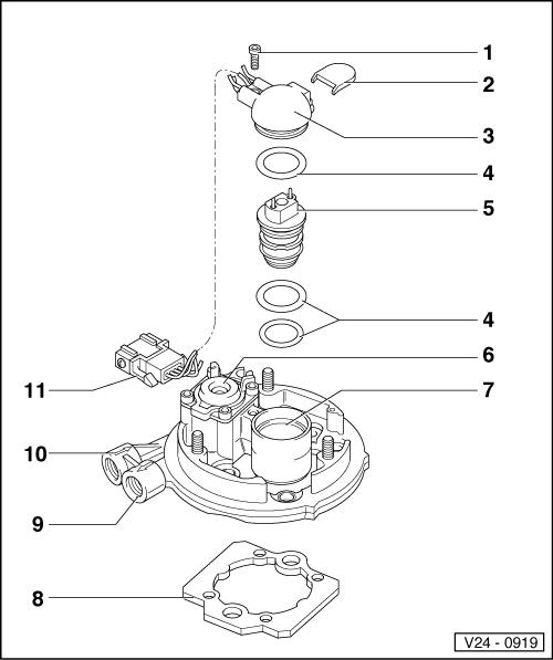
Engine code ABD Servicing upper part
|
|
|
 |
|
|
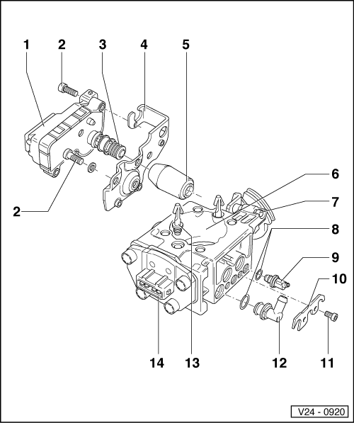
Servicing lower part
|
|
|
|
|
|
|
 |
|
|
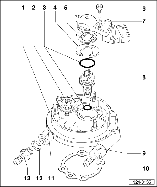
Engine code ABU, AEA Servicing upper part
|
|
|
|
 |
|
|
Servicing lower part
|
|
|
|
|
|
|